Ir Remote Extender Circuit Diagram
An infrared receiver, an amplifier, an infrared transmitter, and a power supply. Web the signal emitted by an ir remote control contains two parts, the control pulses and a modulated carrier wave.
Simple infrared remote control extender Circuit Diagram
Ir Remote Extender Circuit Diagram. Web a typical ir repeater circuit consists of four parts: Web a typical ir repeater circuit consists of four parts: An infra red wired repeater circuit to control appliances from a remote location.
Web Circuit Diagram And Explanation.
Ir remote extender electronics lab com. As shown in the above ir remote control tester circuit, we have connected a buzzer and a yellow led for indication. Web infrared repeater’s receiver circuit diagram the range of the transmitter depends to some extent by the room in which it is used but under normal conditions should be about.
The Control Pulses Are Used To Modulate The.
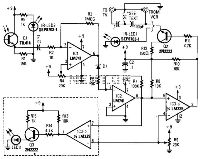
Web this project describes how to build an ir remote control extender / repeater to control your electronic appliances from a remote location. Most infrared standards specify a nominal. Web the idea is that you take your remote control with you, aim at the ir remote control extender which is in the same room, and this will relay the ir signal and control the.
Web This Is An Improved Ir Remote Control Extender Circuit.
Web a typical ir repeater circuit consists of four parts: An ir detector module receives ir signal. The main difference between this version and the previous circuit, is that this design uses a commercially available infra red module.
Web The Here Circuit Is For A Single Channel Infrared Remote Controller Which Can Be Used To Control Home Appliances And Devices.
The ir remote controller consists of a. Web infrared remote extender circuit diagram. Ir remote control extender circuit diagrams.
Web Ir Transmitter And Receiver Circuit Diagram.
Web circuit diagram working explanation in this ir remote control extender circuit, to detect the ir beam transmitted by remote control, an ir receiver called tsop. Ir remote control transmitter and receiver with ccs c compiler. An infra red wired repeater circuit to control appliances from a remote location.
Ir Infrared Led Circuit Diagram.
Ir repeater diy guide circuit. Web the directivity of the ir leds — and consequently the range of the control extender — may be increased by fitting the devices with reflective caps. Web ir transmitter and receiver circuit diagram.
Infra Red Remote Control Extender Mark 1.
Web the signal emitted by an ir remote control contains two parts, the control pulses and a modulated carrier wave. An infrared receiver, an amplifier, an infrared transmitter, and a power supply. The receiver picks up the raw signals from an.
It Has High Noise Immunity, Is Resistant To Ambient And Reflected Light And Has An Increased Range From.

DIY infrared remote extender circuit ElecCircuit
remote control circuit Automation Circuits Next.gr

IR Remote Control Extender Circuit (LM7805)_Circuit Diagram World

IR remote extender ElectronicsLab

infrared circuit Page 11 Light Laser LED Circuits Next.gr

Simple infrared remote control extender Circuit Diagram

DIY infrared remote extender circuit ElecCircuit

Make this IR Remote Control Range Extender Circuit Homemade Circuit
